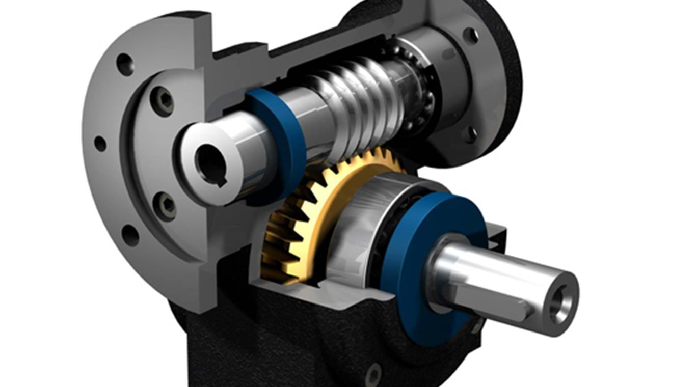
The exploded diagram of the worm gear box assembly. The parts are as
4.6 (480) · $ 5.00 · In stock

Download scientific diagram | The exploded diagram of the worm gear box assembly. The parts are as follows: 1-cover; 2-bearing; 3-worm shaft; 4-cover; 5-bearing; 6-gear box body; 7-bearing; 8-oil seal; 9-cover; 10-plug; 11-worm gear rim; 12-worm gear hub; 13-output shaft; 14-bearing; 15-oil seal; 16-cover from publication: Image-assisted collision detection for calculation of an assembly interference matrix | The assembly interference matrix is a foundational information model for assembly process planning such as assembly sequence and assembly path planning, and supports digital assembly simulation, intelligent assembly, digital twin-based assembly, and so on. The assembly | Collision Detection, Assembly and Matrix | ResearchGate, the professional network for scientists.

Murray 1696675-00 - C950-52592-1, Craftsman 21.0 Gross TP 30 Dual Stage Snow Thrower (2017) Parts Diagram for Gear Case Assembly (704027)

slewing ring bearing drive Tracking system, Driving, Engineering tools

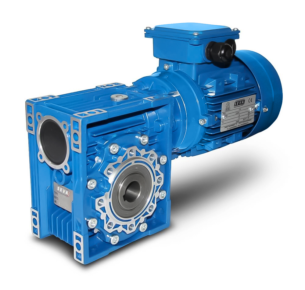
Worm gear, gearbox, gear motor, 3D CAD Model Library

Standard Parts List - Electrolift
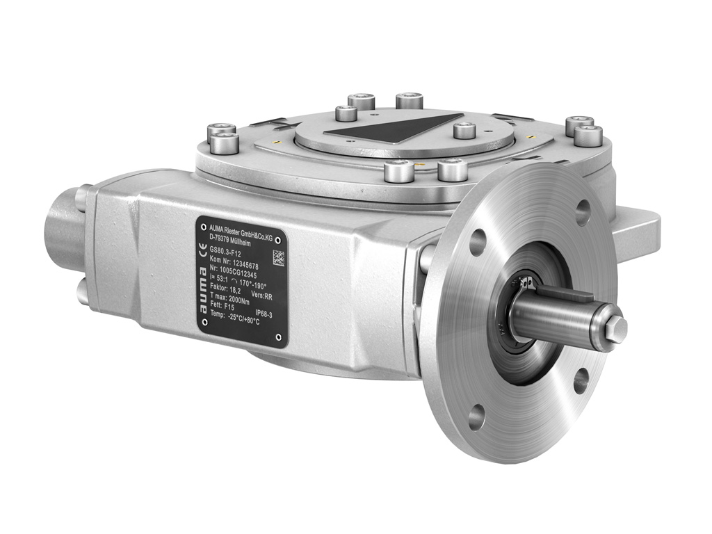
AUMA - Gearboxes GS

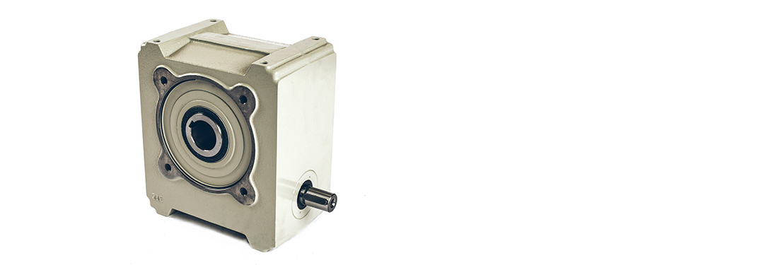
Gearbox - an overview
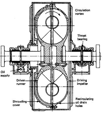
Couplings, Clutches and Gearboxes for Marine Diesel Engine

How it's made, the hand winch
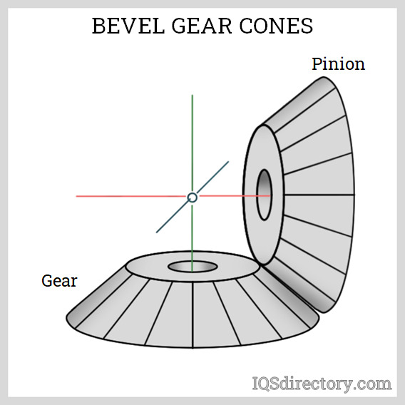
Bevel Gear: What Are They? How Do They Work? Types and Uses

NMRV worm gears operating instructions
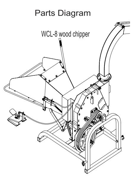
Parts Diagram - Chippers Direct

Worm gear, gearbox, gear motor, 3D CAD Model Library

The exploded diagram of the worm gear box assembly. The parts are as